
RC / RL / RLC Circuit Calculator
Blog post description.
Wiratama
11/15/20252 min read
RC, RL, and RLC Circuits – Definition
RC, RL, and RLC circuits are fundamental electrical systems consisting of combinations of resistors (R), capacitors (C), and inductors (L). These circuits determine how voltage and current behave over time—especially during switching, charging, discharging, and transient events. They are essential in filters, signal processing, power electronics, and control systems.
Background Theory
RC Circuit
An RC circuit stores and releases energy in the electric field of a capacitor. Its time constant is:
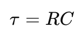

This constant defines how fast the capacitor charges or discharges.
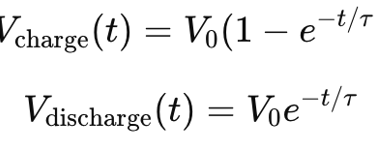
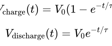
Voltage equations:
RL Circuit
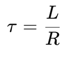
An RL circuit stores and releases energy in the magnetic field of an inductor. Its time constant is:

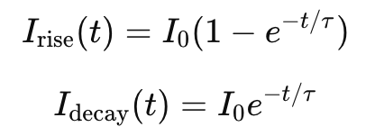
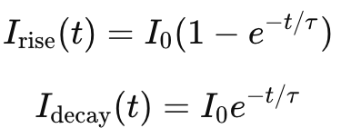
Current equations:
RLC Circuit
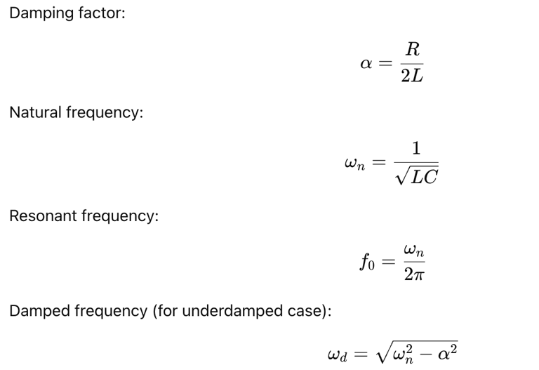
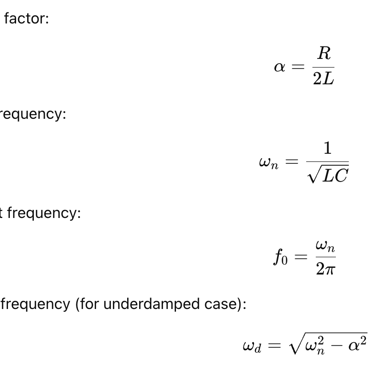
An RLC circuit is a second-order system capable of oscillation. Key parameters include:
Circuit behavior depends on damping:
Underdamped: oscillatory response
Critically damped: fastest non-oscillatory response
Overdamped: slow non-oscillatory response
How This Calculator Works
This calculator provides quick analysis for all three circuit types:
RC Mode
Computes time constant
Displays charging and discharging equations
RL Mode
Computes time constant
Displays current rise and decay equations
RLC Mode
Computes damping factor, natural frequency, resonant frequency, and damped frequency
Classifies the system as underdamped, overdamped, or critically damped
By entering resistance (R), capacitance (C), and inductance (L), the calculator instantly displays the key transient and frequency-domain parameters required for engineering design, tuning, and circuit analysis.